|
|
|
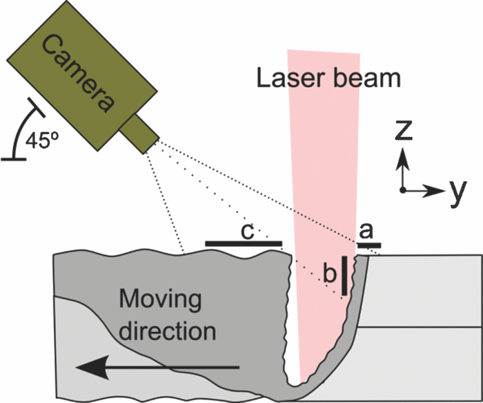
The use of high-speed cameras in laser welding research dates back to 1985 when Arata, Abe, and Oda used a 6000-fps 16-mm camera to observe the process.1 The development of high-speed digital cameras has made the technology easier to use, and in recent years high-speed photography of 1000 to 20,000 fps has become standard in many laboratories. In this present work, the authors have used equipment and techniques that increase this frame rate by an order of magnitude, allowing much more detailed observation of the laser-material interactions involved. This work presents images taken by a Photron (San Diego, California) SA1 high-speed camera with a Micro-Nikkor 105-mm lens, at 180,000 frames per second with an exposure time of 370 ns. The image size was 128×128 pixels with 12-bit pixel depth. Figure 1 shows the basic arrangement of the equipment. The experiments involved a moving workpiece, and a stationary laser beam and camera. Figure 2 shows a typical still image taken during Nd:YAG laser welding of stainless steel (Haas HL3006D, laser power 2.5 kW, welding speed 0.1 m/s, weld depth 2 mm, focusing optics 300 mm, spot size ∼600 μm). The weld pool area has been illuminated by a 500-W Cavilux (Cavitar, Tampere, Finland) HF pulsed illumination diode laser to observe the melt flow around the keyhole. In this case, the illumination direction was from the right and created the bright spots on the melt surface to the left of the keyhole. The keyhole itself emits light as a function of the local temperature. Bright spots inside the keyhole indicate humps in the keyhole wall, which become locally heated by the incident laser beam, as described in Fig. 3. Fig. 2Frame from the video of the weld capillary. The welding direction is toward the top of the image. The keyhole contains bright, hot areas. The molten surface behind the keyhole appears dark. The solidifying edges of the melt appear brighter with very bright spots on the left of the keyhole, which are the result of reflections from the laser illumination from the right (see Fig. 1). (QuickTime, 7.2 MB)..  Fig. 3Inside the keyhole, the liquid flow creates raised waves or humps that absorb incident laser light and become hotter than the surrounding melt. These humps appear as bright areas in Fig. 2. 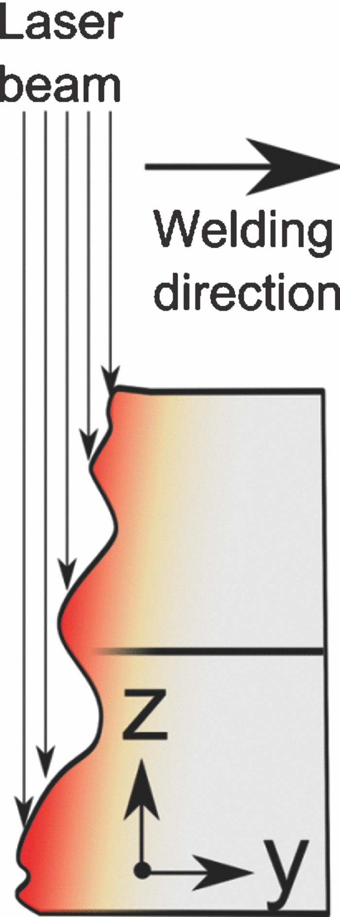 A number of theoretical models have assumed that the surface of the keyhole is smooth,2, 3 but Fig. 2 clearly shows that the liquid on the front wall of the keyhole has a rippled surface. Close observation of high-speed sequences of images have shown that the ripples travel rapidly over the surface of the melt, as predicted by other theoretical models.4, 5 The complex, 3-D flow of liquid over the front wall of the capillary makes it difficult to estimate flow speeds and directions. However, it is possible to quantify flow speeds and direction by using a specially developed type of streak photography. A thin, central strip, one pixel wide, can be extracted from photographic images of the type shown in Fig. 2. A collection of these single pixel lines can then be placed side by side to present streak photograph information, mapping the movement of bright zones along the center line of the main image. Figure 4 presents the data in this format, and shows the variation in brightness along the capillary center line over time (540 frames). This streak image visualizes time-dependent events. Fig. 4Inclined bright lines can be associated with moving bright points along the center line on the grayscale image presented in Fig. 2. a: solid metal ahead of weld. b: front edge of keyhole. c: melt surface behind keyhole. 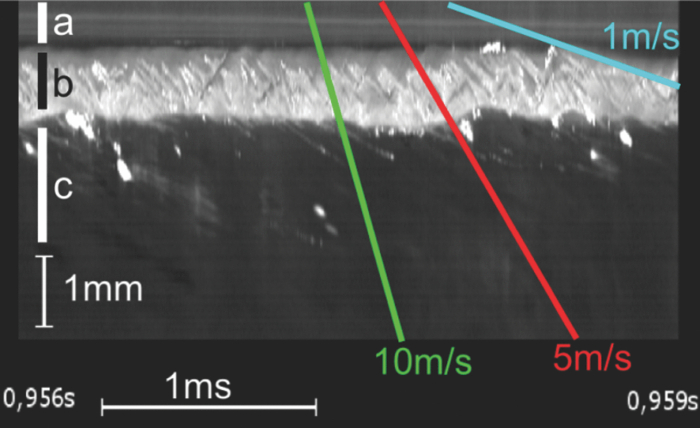 A simplified geometry of the observed area is presented in Fig. 5, which helps the interpretation of the information provided in Fig. 4. It is important to bear in mind that the streaks mapped in zone b represent movement down the almost vertical face of the keyhole front, whereas movement outside this area, in zone c, is approximately horizontal—across the surface of the melt pool behind the keyhole. As both of these directions subtend an angle of approximately 45 deg to the camera pointing direction, it is possible to scale and superimpose inclined lines on the streak image to represent the speed of movement involved, as we have done in Fig. 4. Parallel lines have the same velocity, and thus velocities in the weld area can be measured. Figure 4 indicates two types of wave motion in the area observed: 1. the movement of raised waves vertically down the keyhole front at speeds of approximately 5 m/s (500 μm per frame at 10,000 fps), and 2. the movement of waves on the melt surface behind the keyhole—in this case in the same direction as the movement of the workpiece and at speeds of approximately 1 m/s. This is the first experimental measurement of the first of the two fluid flows and of the keyhole wall ripples, and this has been made possible by the use of the new generation of high-speed digital cameras with frame rates in excess of 100,000 fps. This gives researchers the opportunity to compare experimental measurements with numerical models.6, 7 We have also employed these high speed imaging techniques to observe melt movement inside a weld keyhole that penetrates between two 0.8-mm overlapping sheets of zinc-coated steel. The zinc coatings trapped between the two sheets evaporate when the steel melts, and the resultant jet of zinc vapor into the keyhole provokes blowouts in the weld pool.8 During a blowout, the entire front wall of the keyhole is visible to the camera (Fig. 6). In this experimental case, no illumination was used, so all light is emitted from the hot surface of the molten metal. Fig. 6(a) Simplified geometry. (b) Frame from video of zinc-coated overlap welding. (QuickTime, 9.6 MB).. 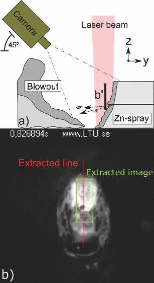 Figure 6 gives a global view of the keyhole area, and Fig. 7 presents a sequence of close-up views extracted from zone b in Fig. 6, which are spread over 33 μs. In Fig. 7 the upper bright area is the keyhole front of the upper sheet, and the dark area is the interface between the two sheets where the weld front is cooled by the ejection of zinc vapor. The lower midbrightness area is the top of the keyhole front of the lower sheet. The sequence shows a droplet of molten steel being detached from the upper sheet over the dark gap. The streak photograph for this flow is presented in Fig. 8, and it is clear that the droplets are leaving the bottom of the upper sheet at approximately 7 m/s. We believe that these droplets, after being detached, travel across the keyhole horizontally rather than vertically down the keyhole front. The driving force for material transport in this horizontal direction is provided by the jet of zinc vapor being created in the center of the front wall of the keyhole. The horizontal impact of the molten steel droplets and zinc vapor on the rear wall of the capillary would explain the severe problem of droplet ejection from welds in zinc-coated steel (see Fig. 6). Fig. 7Seven images extracted from the center of the keyhole front wall during a 33-μs sequence of a weld between two overlapping plates of zinc-coated mild steel. 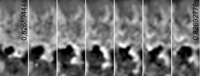 Fig. 8The streak image created from the film for welding two overlapping sheets of zinc-coated steel. 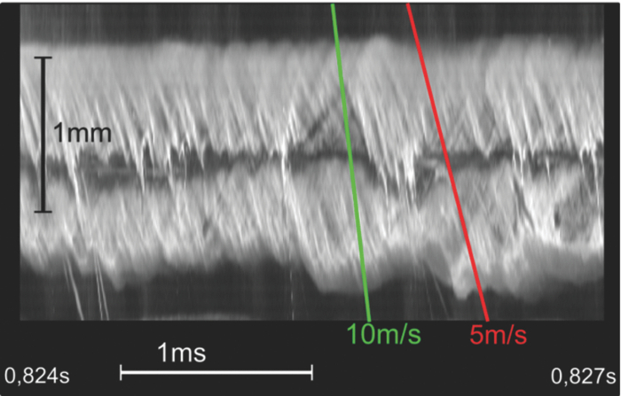 We believe that high-speed imagery and streak photo-graphy of the type demonstrated here will help to unlock the secrets of laser evaporated keyholes, and lead to a deeper understanding of many of the other physical interactions involved in laser welding. ReferencesY. Arata, N. Abe, and T. Oda,
“Fundamental phenomena in high power CO2 laser welding,”
Trans. JWRI, 14 5
–11
(1985). Google Scholar
A. Kaplan,
“A model of deep penetration laser welding based on calculation of the keyhole profile,”
J. Phys. D: Appl. Phys., 27 1805
–1814
(1994). https://doi.org/10.1088/0022-3727/27/9/002 Google Scholar
X. Jin, P. Berger, and T. Graf,
“Multiple reflections and Fresnel absorption in an actual 3D keyhole during deep penetration laser welding,”
J. Phys. D: Appl. Phys., 39 4703
–4712
(2006). https://doi.org/10.1088/0022-3727/39/21/030 Google Scholar
A. Matsunawa and V. Semak,
“The simulation of front keyhole wall dynamics during laser welding,”
J. Phys. D: Appl. Phys., 30 798
–809
(1997). https://doi.org/10.1088/0022-3727/30/5/013 Google Scholar
J. Lee, S. Ko, D. Farson, and C. Yoo,
“Mechanism of keyhole formation and stability in stationary laser welding,”
J. Phys. D: Appl. Phys., 35 1570
–1576
(2002). https://doi.org/10.1088/0022-3727/35/13/320 Google Scholar
E. H. Amara and R. Fabbro,
“Modelling of gas jet effect on the melt pool movements during deep penetration laser welding,”
J. Phys. D: Appl. Phys., 41 055503
(2008). https://doi.org/10.1088/0022-3727/41/5/055503 Google Scholar
M. Geiger, K. H. Leitz, H. Koch, and A. Otto,
“A 3D transient model of keyhole and melt pool dynamics in laser beam welding applied to the joining of zinc coated sheets,”
Prod. Eng. Res. Devel., 3 127
–136
(2009). https://doi.org/10.1007/s11740-008-0148-7 Google Scholar
R. Fabbro, F. Coste, D. Goebels, and M. Kielwasser,
“Study of CW Nd-Yag laser welding of Zn-coated steel sheets,”
J. Phys. D: Appl. Phys., 39 401
–409
(2006). https://doi.org/10.1088/0022-3727/39/2/024 Google Scholar
|