|
|
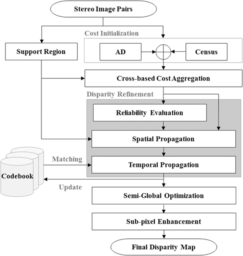
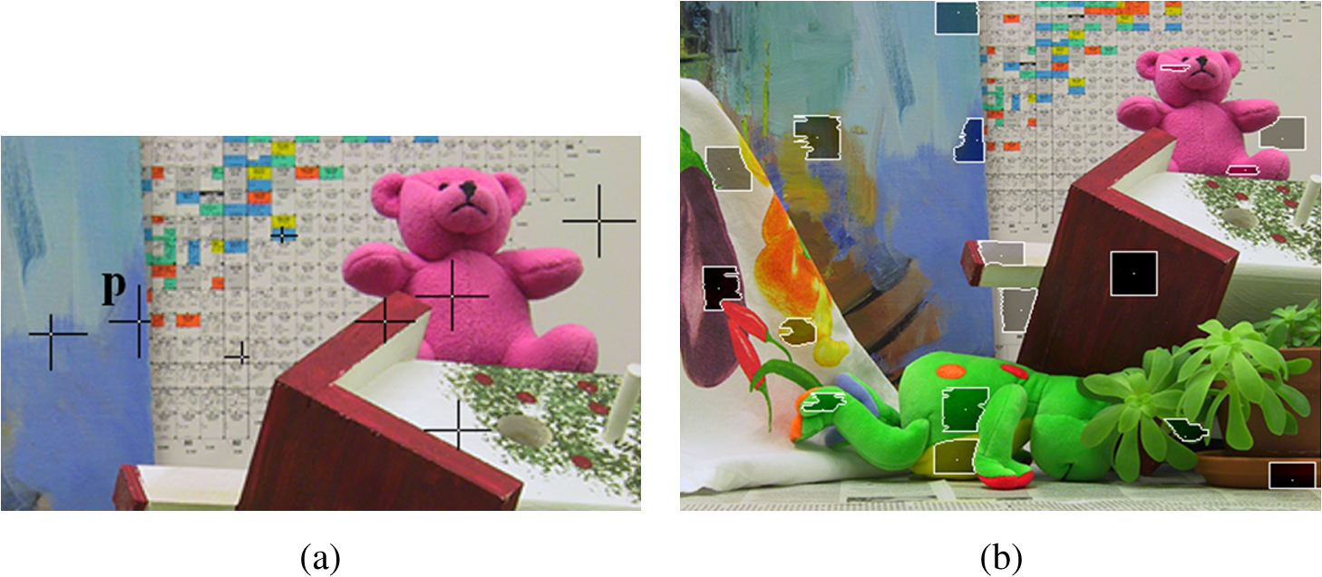
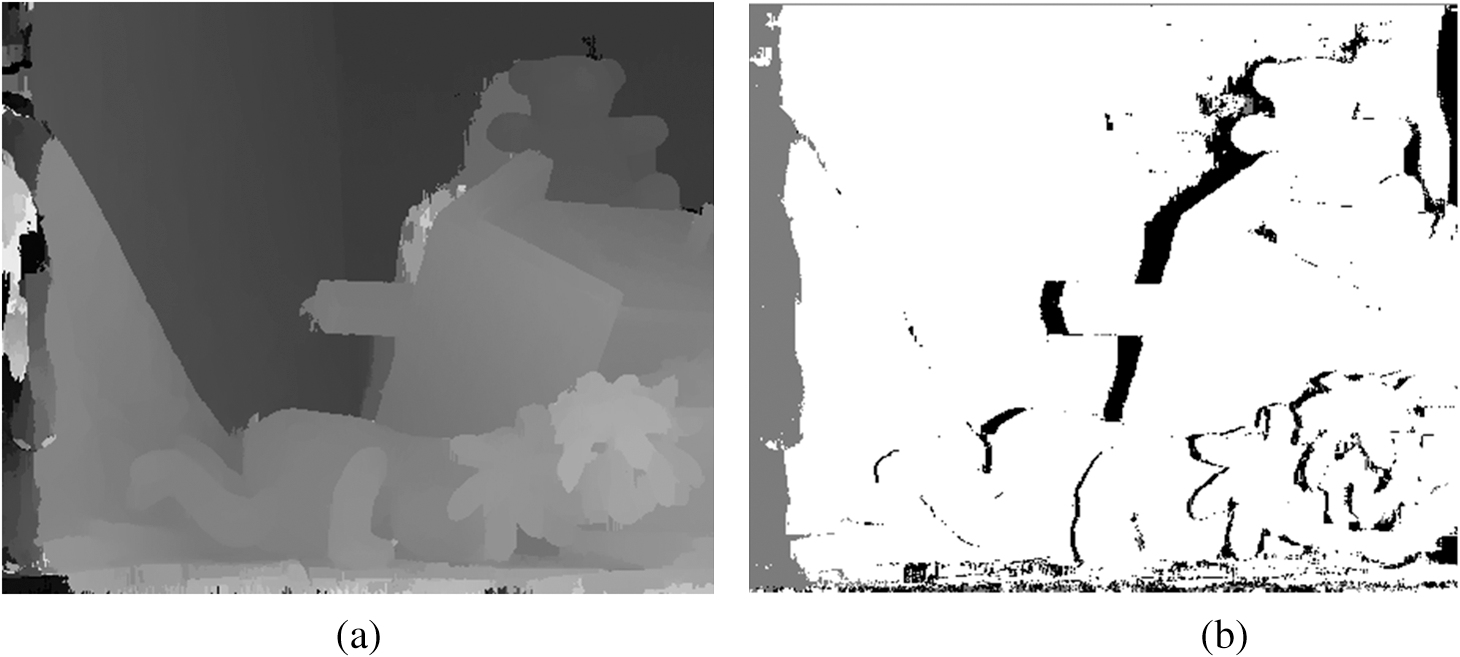
1.IntroductionDense stereo matching is one of the most extensively studied topics in computer vision.1–18 It is an effective three-dimensional reconstruction method, since it can usually recover a dense disparity map from a stereo view. Kinect sensor using an infrared band captures precise range information, but it is only for indoor use and its operation range is substantially limited. Stereo systems are useful in both indoor/outdoor applications, such as robot navigation and autonomous vehicle control. Stereo matching algorithms are classified widely into local and global matching methods, In addition, stereo algorithms are described in more detail according to four individual components in stereo matching, matching cost computation, cost aggregation, disparity computation, and disparity refinement.1 Most global stereo methods are computationally expensive and involve many parameters, while local stereo methods are generally efficient and easy to implement. In the local approaches, most common pixel-based matching costs include absolute difference (AD), normalized cross-correlation (NCC), and Birchfield and Tomasi’s measure (BT) to examine the matching cost in a search window. The central problem of local window-based methods is how to determine the size and shape of the aggregation window. Hirschmüller and Scharstein proposed a census method that is robust to brightness changes,2 but it causes matching ambiguity in image regions with repetitive or similar local structures. Yoon and Kweon assigned different support weights to pixels in the window by using the photometric and geometric relationship with the pixel under consideration, but many problems, including textureless regions, repeated similar patterns, and occlusions, still remain unsolved.3 In the global matching approaches, an energy function is used to find the optimal solution in terms of matching cost. It consists of a data term and a smoothness term. The data term represents the degree of image difference between the left and right stereo images according to the disparity level. The smoothness term represents the compensation level of the discontinuity in neighboring pixels. The algorithms make an explicit smoothness assumption, but the search step to find a global solution minimizing the energy function incurs a heavy computational load. The popular energy minimization frameworks, such as graph cuts,4 belief propagation,5 and dynamic programming,6 have attracted attention due to their good performance. Hirschmüller suggested the semiglobal method, which substitutes global and two-dimensional smoothness constraints by the combined one-dimensional constraint in different aggregation directions for pixel-wise matching.7 Researchers also developed image segmentation and plane-fitting methods.8–10 Segmentation methods are based on the assumption that scene structure can be approximated by a set of nonoverlapping planes in the disparity space and that each plane is coincident with at least one homogeneous color segment in the reference image. While segmentation information is generally useful for accurate disparity results, these methods require a large number of computationally demanding iterations. When the color distribution of the foreground object is similar to that of the background element, it is difficult for us to estimate a precise result. The disparity plane-fitting based stereo methods model the scene structure using a set of planar surface patches. These methods estimate an individual plane at each pixel onto which the support region is projected. However, they have a lot of difficulties in finding one of minimum aggregated matching costs among all the candidate planes. Blyer et al. and Richardt et al. built a disparity map using temporal propagation,10,11 but the occlusion problem in various dynamic situations still remain unsolved. In order to reduce the heavy computational load in the dense matching of stereo views, graphics processing unit (GPU)-based methods were proposed.11–16 The traditional sum of square difference was used to independently aggregate matching costs in GPU and embedded stereo systems. The GPU-based adaptive window approach can change the shapes of cost aggregation windows according to the content of the local image area, taking into account edges and corners.13 In Ref. 14, the belief propagation based method is implemented to run at real-time on a GPU. Specifically, compute unified device architecture (CUDA) has been one of the most popular high-performance computing engines to implement real-time stereo matching methods.15,16 Some recently proposed methods are suggested to improve both matching accuracy and processing efficiency on a GPU.17,18 In addition, the stereo video process has different challenges from that in stereo image: the application of techniques on a per-frame basis is not enough to achieve flicker-free and temporally coherent disparity maps. Generally, a video sequence is temporally and spatially correlated with scene elements, such as a human being or objects in an interested scene. However, most of the previous stereo matching methods dealt with correspondence problem on a per-frame basis, so they cannot obtain temporally coherent disparity maps over a stereo video sequence. The proposed method obtains a more accurate disparity map by using temporal and spatial propagation of reliable disparity information over the stereo sequence. The contribution of this paper consists of three parts. First, we define a measure to evaluate the reliability of an initial disparity map and combine this measure with a left-right consistency (LRC) check. Second, we propose a spatial propagation of the reliable disparity to remove the outliers. Third, we introduce a temporal propagation based on a codebook. Figure 1 shows a flow chart of the proposed algorithm. To tackle half-occluded (objects scene in one image and not in other) regions in a dynamic situation, we consider background information that is occluded by foreground elements. Several methods have been used for foreground/background segmentation.19–21 In the generalized mixture of Gaussians, backgrounds with fast variations are not easily modeled with just a few Gaussians. In addition, it is difficult to determine an optimal learning rate to accurately adapt to background changes.19 The nonparametric technique computes the probability density function at each pixel from many samples using a kernel density estimation.20 When sampling the background for a long time period, however, this method has a memory constraints problem. The previous codebook with the quantized background values at each pixel was designed to obtain sample values over a long video sequence without making parametric assumptions.21 We modify the codebook to resolve the occlusion problem in stereo matching by using a temporal correlation over the stereo sequence. We store and use color, reliability, array of the matching cost, and final access time of the scene elements, including background and foreground objects. Our proposed codebook contains temporally coherent information of scene elements over the stereo sequence. 2.Proposed Method2.1.Initial Matching Cost ComputationThe initial matching cost volume at each pixel and each disparity level is computed using AD-census in parallel, which combines the AD measure and census transform.17 Because the AD measure examines only the pixel intensity, it is substantially affected by lighting changes. The census transform encodes local image structures with relative orderings of the pixel intensities rather than the intensity value itself to tolerate outliers caused by radiometric changes and image noise. In the stereo view, the brightness distribution of the left image is different from that of the right image because of different illumination conditions and surrounding environments. A longer baseline length allows us to handle a larger space, but the difference between the two views will increase substantially. So many outlier regions occur in an initial cost volume obtained by the AD-census. To reduce the outlier regions, we aggregate each pixel’s matching cost throughout the support region on the assumption that neighboring pixels with similar colors should have similar disparities.3,17,22 For each anchor pixel , an upright cross skeleton of the support region is adaptively constructed with four varying arm lengths determined by color similarity and connectivity constraints. When local cross results are given, a shape-adaptive full support region can be dynamically built by the process of merging horizontal segments of the crosses in the vertical neighborhood.22 When a pair of hypothetical correspondences is established [ in the left image and in the right], we can measure the matching cost between and by aggregating the initial cost in the local support region. The coordinates of and are correlated with a disparity hypothesis and . Figure 2 shows an example for a cross skeleton construction of the support region in the Teddy stereo image. The pixel-wise adaptive crosses define the cross skeleton for and shape-adaptive support regions are dynamically constructed. In Fig. 2(b), the shaded regions are sample shape-adaptive support regions. In order to symmetrically consider both the left local support region and the right region , we combine two local regions and compute the normalized matching cost as follows: where is the combined local support region that contains the valid pixels between the support regions only, and is the number of pixels to normalize the initial cost.2.2.Disparity Refinement2.2.1.Disparity reliability evaluationEven after the above-described aggregation process, the following factors still cause many disparity errors: difference of illuminations in two views, repeated similar patterns, and occlusion by the foreground. Figure 3 shows typical matching cost distributions in aggregated regions. There is a single minimum matching cost within the disparity level in Fig. 3(a), so we can obtain a precise disparity. In Fig. 3(b), we cannot determine the correct disparity level among several candidates as to an image region with repeated pattern. Figure 3(c) shows matching cost distribution of the textureless region. We cannot determine the precise disparity level because many similar matching costs exist. Fig. 3Typical three matching cost distributions on disparity level: (a) distinguished feature region; (b) repeated pattern region; and (c) textureless region. 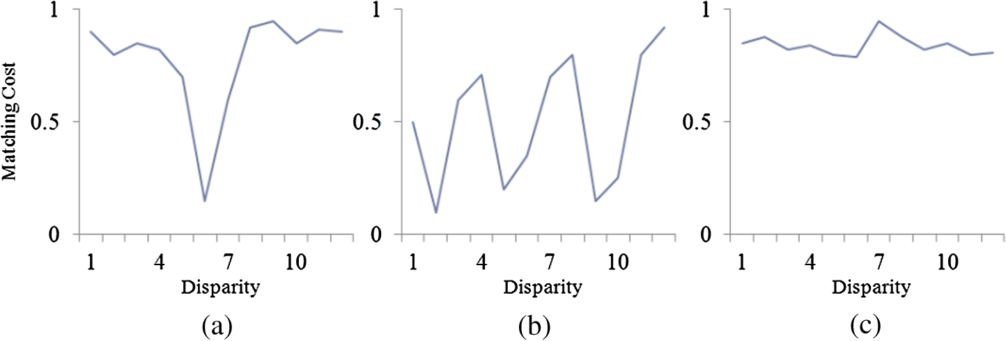 The matching cost for the disparity level at each pixel is examined to determine whether it is significantly smaller than any other competitors. In Figs. 3(b) and 3(c), however, the matching ambiguities cannot be completely overcome. The confidence map of the support region describing the reliability of the obtained disparity is computed to improve the matching performance.23 At the pixel in the support region, initial disparity maps for the left image and the right image are computed using a winner-takes-all (WTA) strategy as provided in Eq. (2).1 Here represents the maximum disparity level. in Eq. (3) means the reliability degree of the disparity at . When the reliability degree approaches 1, the obtained disparity value becomes more precise. An LRC check is used to see if the existence of false matching caused environmental lighting changes, background effects, and occlusions. It is performed by taking the computed disparity value in one image and reprojecting it into the other image. We employ the LRC check to consider the unreliable disparity at half-occluded pixels in the final disparity map. The top portion of Eq. (3) shows that LRC check fails at pixel and its disparity is unreliable. We put the reliability to remove unreliable disparity in the temporal and spatial propagation process. The bottom portion of Eq. (3) shows that the disparity is reliable when the LRC check passes, and then the reliability becomes . Equation (4) computes the reliability of the first cost space. Here, we examine every depth level excluding both the depth by Eq. (2) and the next/previous depth [], to find the disparity level with the minimum matching error among the matching cost . A truncation constant value is used to make the reliability between 0 and 1. If the difference between the smallest cost and the second smallest cost is large enough as in Fig. 3(a), the precise matching disparity can be obtained. On the contrary, when repeated patterns are present as in Fig. 3(b), the difference becomes a relatively small value. Since the reliability should include a confidence degree of the obtained disparity, we examine more various depth levels along the scan line, except the neighboring levels around the initially obtained depth. Figure 4 shows the initial disparity map for the Teddy image by WTA and its reliability map. The dark region with relatively unreliable disparity can be refined further using both temporal and spatial propagation. 2.2.2.Spatial propagationAfter the LRC check to detect the outliers, the outlier is filled with the neighboring reliable disparity in the segmented or the support region by the iterative region voting.17,24 This means the disparity of the outlier is replaced with that of the highest bin value (most votes) in the support region when neighboring pixels with similar colors have similar disparities. However, when the outlier region is too large or the depth of the foreground is much different from that of the neighboring area in spite of its color similarity, the previous iterative voting would be unsuccessful. We propose a spatial propagation approach to overcome the outlier problem by using reliable disparity rather than simply filling outliers with the disparity value of the highest bin value. Table 1 shows the spatial propagation of reliable disparity and updating of the codewords. The proposed method builds a histogram of only the reliable disparity in the support region . In II(ii) of Table 1, we obtain the most reliable disparity and replace the outlier disparity at by . Table 1Spatial propagation of reliable disparity and updating codewords.
Because there may be many points with in the support region, we determine the specific pixel position to update the codewords (the reliability and the matching cost space) of for further disparity refinement procedures. In III of Table 1, the subset satisfying is determined from any element of the entire set and is the threshold value. Then we compute the color distance between and , and the pixel with the smallest color distance is determined as the final position. Here, is L-1 color distance measure between two pixels in the RGB space. Both the matching cost and the reliability at pixel are updated as III(iii) in Table 1. is a robust function on variable and it is used to control the influence of the color similarity between two pixels with the control parameter . If there is no pixel satisfying the above condition, the reliability is updated to 0. In Fig. 5(b), the disparity space image of the Teddy stereo image shows the matching error at a position on the scan line (green line) relative to the disparity level []. A more precise disparity map can be obtained at the position with a lower intensity value (matching error). Many undistinguished disparities happen in A region because of the matching ambiguity problem. Much more unreliable disparities happen in B region because of many repeated patterns. As shown in Fig. 5, the spatial propagation method improves the reliability of the disparity in the invalid areas (A and B). For further details, the proposed method fills A region with more reliable neighboring disparity and reduces the unwanted staircase effects caused by the repeated pattern in B region. Fig. 5(a) Teddy image. (b) Matching cost space enhancement by spatial propagation: example area, reliability map, disparity space image (DSI) on scan line, and enhanced DSI (from up to down). 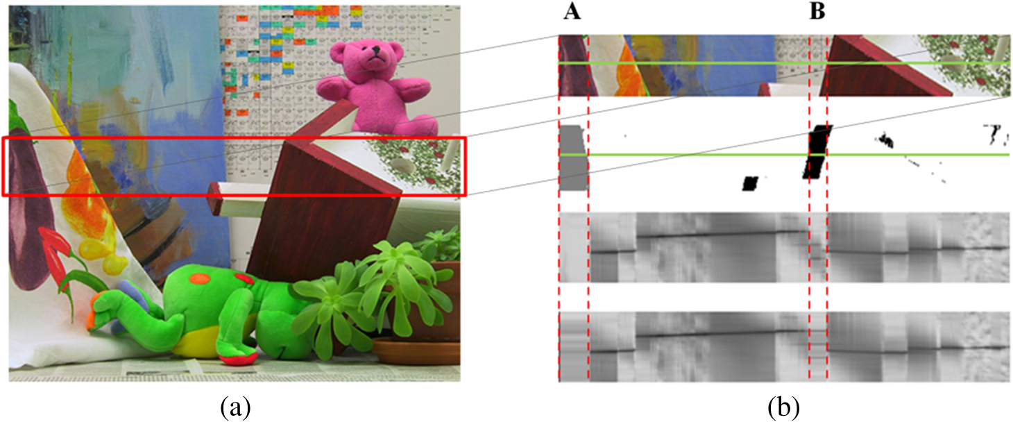 The enhanced matching cost and reliability information obtained from the spatial propagation are used to overcome the occlusion problem by the foreground objects in the temporal propagation process. 2.2.3.Temporal propagation using codebookIn order to overcome the occlusion and the depth discontinuity of an object, we propose a temporal propagation process using color, reliability, matching cost set, and final access time values as codeword in the modified codebook. In the conventional codebook approach, the background region is modeled and parameterized only with the minimum and the maximum color values, which are updated at a regular interval to account for the effects of object movement and illumination change.21 The process is not good enough to overcome the occlusion problem in various situations because it stores only the color information before the occlusion. Bleyer et al. proposed a temporal propagation using the slanted planes over successive frames for a stereo image sequence.10 It does not sufficiently consider the update frequency of the prior information about the scene. This proposed codebook consists of color value , reliability , array of the matching cost , and final access time at pixel . The matching cost and the reliability of the codebook are updated as described in Table 2. Table 2Updating both matching cost and reliability.
For the pixel , we find the codeword satisfying the condition II(i)(a) in Table 2 and update both the matching cost space and the reliability. In Table 2, represents the relative weight of the previous codewords and , and the current passed information and at pixel . and represent the color distance measure and the robust function in spatial propagation as in Sec. 2.2.2. In II(ii)(a) of Table 2, the matching cost is updated with the weighted sum of the previous cost at and that of the chosen position. In the same way, the reliability is replaced using II(ii)(b) in Table 2. Here, the color similarity between two pixels is considered as in the spatial propagation process. The codeword of a codebook is updated using the matched codeword as in Table 3. The codebook is an empty set at an initial time (). For the reliable pixel , the codeword satisfying the condition II(i) in Table 2 is used to update the codebook as II(i) in Table 3. If there is no match, a new codeword , including color, reliability, matching cost, and frame number, is generated in the codebook . Table 3Updating codeword and generating new codeword.
When the codeword is not matched for a while (), our method concludes that the codeword insufficiently reflects the current image information due to the scene element changes, such as object movement. As shown in Table 4, after examining the effectiveness of the codeword, the unused codeword is removed to improve memory usage efficiency. Table 4Evaluating effective codeword.
To further alleviate the matching ambiguity in the disparity map, an optimizer with smoothness constraints and moderate parallelism should be adopted. We employ a multidirection scan line optimizer based on Hirschmüller’s semiglobal method.7,17 Four scan line optimization processes are performed independently: two along horizontal directions and two along vertical directions. We examine the matching cost distribution of neighboring pixels along the scan line direction, including the appropriate penalty for discontinuities (a threshold value for color difference). After computing the matching space with the smoothness in four scan directions, a subpixel enhancement based on quadratic polynomial interpolation is employed to reduce the errors caused by disparity levels.24 The interpolated disparity is computed with three discrete depth candidates: the depth () with the minimal cost and its two neighboring depth levels ( and ). The final disparity is obtained by smoothing the interpolated results with a median filter. 3.Experimental ResultsThe following computational equipment is used for the experiment: a PC with Intel Core i7 3.4 GHz CPU and 4 GB RAM with Nvidia GTX680 graphics card. The proposed system is tested with the Middlebury benchmark25 and the stereo images () captured by a Bumblebee 3 from Point Grey Inc. in Canada at 15 frames per second. The proposed method is implemented on a GPGPU with CUDA to handle the heavy computational loads of both the stereo matching and the cost refinement.26 Figure 6 shows Tsukuba, Venus, Teddy, and Cones stereo datasets and the disparity maps from this method. Table 5 shows the quantitative evaluation results by stereo matching algorithms with a near-real-time computation performance for the Middlebury database set. Here, the performances are evaluated only in the non-occluded region “non-occ,” all (including half-occluded) regions “all,” and regions near depth discontinuities “disc,” respectively. Our method produces the best results on the Venus image pair because the simple scene element would be suitable for spatial propagation. In comparison, the proposed method provides better results than any other method except AD-census.17 Additionally, the proposed temporal propagation with codebook is useful for improving the matching performance in a stereo image sequence as in Fig. 6. Fig. 6(a) Tsukuba, Venus, Teddy, and Cones stereo datasets (from left to right). (b) Disparity maps by the proposed algorithm. 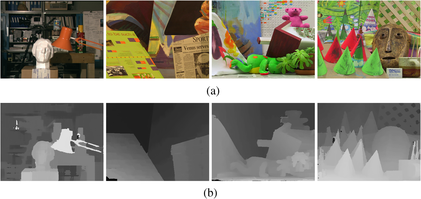 Table 5Quantitative evaluation results for Middlebury database set belief propagation (BP), bitwise fast voting (BFV), Adaptive support-weight (AW), and dual-cross-bilateral grid (DCB).
occ, occluded; AD, absolute difference. In Table 6, the computation performances of the modules on a stereo image () with the maximum depth of 40 are compared on CPU and GPU implementation. The proposed temporal propagation employs codewords with background and stereo matching information. As shown in Tables 2 and 3, the codebook matching step requires much more memory access and codeword comparisons than any other module. Table 6 shows that the codebook matching step provides relatively less performance improvement in spite of its GPU implementation. Thus, GPU implementation is suitable for single instruction multiple data processing, such as initial cost volume process. Table 6Computation time (millisecond) of modules.
The proposed method is designed for dynamic situations, such as mobile robots. When the camera is moved, it is difficult for us to precisely model the background information with the codebook in real-time. For this reason, we do not include the temporal propagation step based on the codebook in a dynamic environment with camera movement. In a dynamic situation with camera movement, the proposed method with spatial propagation requires only 81.71 ms. As shown in Tables 5 and 7, even though AD-census17 provides a better accuracy performance, it requires more processing time and it cannot be used for real-time systems, such as mobile robots and natural user interface. The proposed method is suitable for near-real-time application because it provides improved matching accuracy and processing efficiency. Table 7Comparison of averaged squared errors belief propagation (BP), bitwise fast voting (BFV), Adaptive support-weight (AW), and dual-cross-bilateral grid (DCB).
The accuracy of the disparity map can be evaluated quantitatively by using the reference depth map of Middlebury database sets. Table 7 provides comparison of the average squared errors by stereo matching methods. The AW method3 is usually classified as a non-real-time stereo algorithm. The system also helps us to overcome various occlusions by using temporal propagation based on the codebook. In an indoor environment, the scene background is initially modeled for 5 to 10 frames and the codebook is updated at regular intervals to reduce the unwanted effects of background and lighting changes. Figure 7 shows an input stereo image (left view) and the results by successive procedures. The minimum averaged squared error on each image is highlighted in boldface. Figures 7(b) to 7(d) show the disparity between the AD-census, initial disparity map by cost aggregation, and the reliability map, respectively. In the reliability map, there are the dark regions with relatively unreliable disparity around people according to their movements. Figures 7(e) and 7(f) show the disparity map for only the spatial propagation, and that for both spatial and temporal propagation, respectively. These unreliable disparity areas in Figs. 7(c) and 7(d) are refined further using spatial and temporal propagation. For example, the reliability map [Fig. 7(d)] shows the ceiling area with a relatively unreliable disparity. Fig. 7(a) Stereo image (left view). (b) Disparity by absolute difference-census. (c) Initial disparity map by cost aggregation. (d) Reliability map. Disparity map (e) by spatial propagation and (f) by both spatial and temporal propagations. (g) Final disparity map by optimization/subpixel enhancement of (e). (h) Final disparity map by optimization/subpixel enhancement of (f). 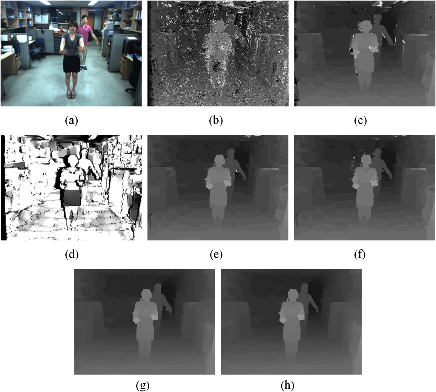 Figures 7(g) and 7(h) show the final disparity map by optimization/subpixel enhancement of Fig. 7(e) and that of Fig. 7(f), respectively. The final disparity results show these regions are much enhanced through semiglobal optimization and subpixel enhancement. In final disparity maps [Figs. 6(g) and 6(h)], we obtain a more accurate disparity map by using both spatial and temporal propagation based on the codebook over the stereo sequence. In the comparison of matching performances in the outdoor scene (Fig. 8), the proposed algorithm produces better disparity map than the dual-cross-bilateral grid (DCB) grid, adaptive weight method, and cross-based matching.3,11,29 According to two important threshold parameters, the color difference ( to 63) in scan line optimization and the reliability ( to 0.87), the matching performances of the proposed method in all (including half-occluded) regions for the Cones and Teddy images are shown in Fig. 9. By analyzing matching error distributions of the Middlebury images, we can determine two threshold values for the minimum matching error: and are set to 0.172 and 27.552. In addition, , , and are set to 2, 1, and 15, respectively. Fig. 8(a) Outdoor scene image. Disparity map by (b) DCB grid;11 (c) adaptive weight;3 (d) cross-based matching;19 and (e) proposed method. (f) Three-dimensional (3-D) reconstruction view of (e). 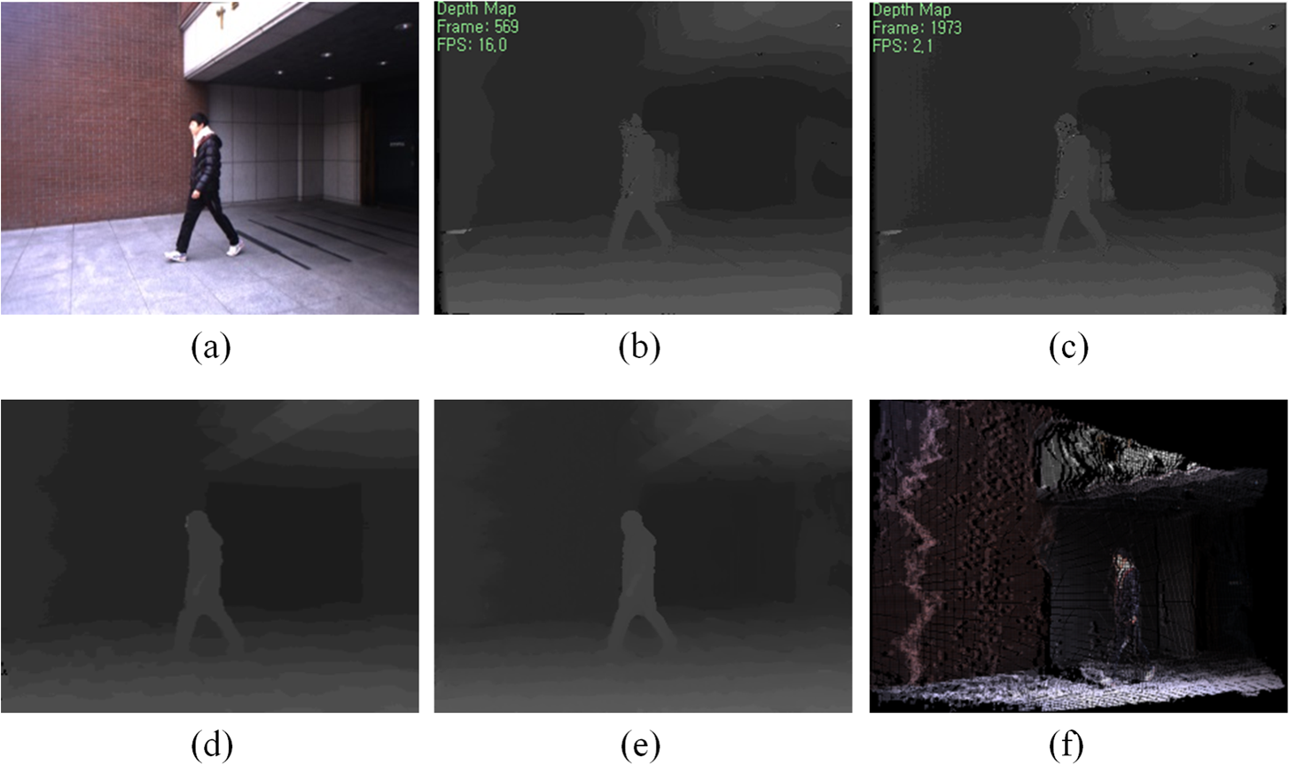 Fig. 9Performance according to threshold parameters ( is reliability and is color difference in scanline optimization) on (a) Cones image and (b) Teddy image set. 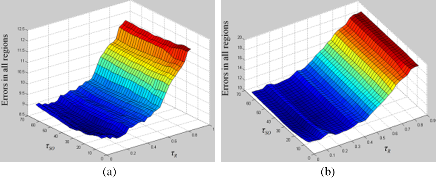 In order to show the effectiveness in qualitative characteristics, we compare the disparity map for non-real-time algorithm30 with that for the proposed method on a publicly available, real-world stereo video set: an Ilkay sequence from Microsoft i2i database. The disparity result [Fig. 10(b)] by ST-2 has more accurate depth borders and less noise. On the contrary, the proposed method has a near-real-time processing performance and obtains more accurate disparity in textureless areas, such as wall and ceiling. Fig. 10Snapshots of Ilkay stereo sequence from Microsoft i2i database: (a) reference frame. Disparity result by (b) aggregation with enhanced segment tree30 (b) proposed method; and (f) 3-D reconstruction view of (e). 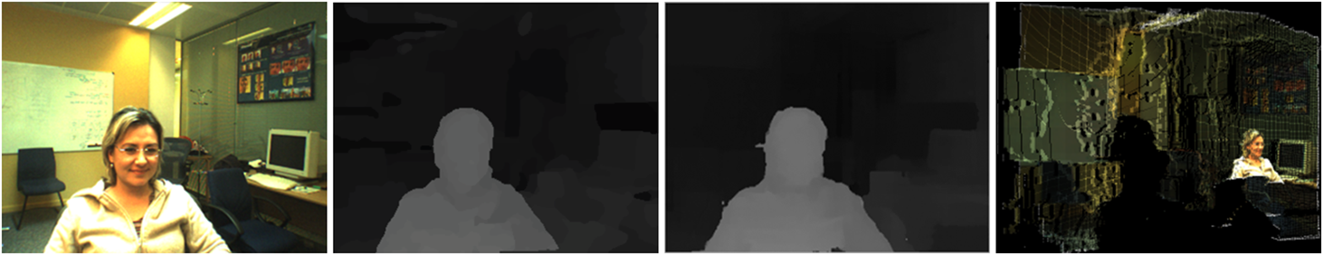 Even though the kinect sensor captures precise depth information about the scene element, it can be operated within a substantially limited operation range and only in an indoor environment. It is also greatly affected by the reflection properties of the environmental elements, such as the monitor. Our proposed stereo system provides an extended usage range and a precise depth map result. Thus, it can be used for real-time indoor/outdoor applications. In the codebook update process, we average the previously stored codeword and the new computed one to reflect the new codeword value as in Table 2. This may lead to run-away codewords if some misclassifications occur, so we will employ another weighted update method for the codebook. The proposed method considers much important information for stereo matching over the stereo video sequence in addition to the color value. However, because we just observe the pixel-wise data, there may be some errors in the disparity map for the proposed method. In order to improve the matching performance, we extend the pixel-wise codebook method into the patch- or segment-based method with spatial correlation. 4.ConclusionThe proposed method improves matching performance by using temporal and spatial propagation of reliable disparity over a stereo sequence. First, we compute a reliability map of an initial matching cost. After examining the LRC to detect the outliers created by occlusion, the proposed spatial propagation fills the outliers with the neighboring reliable disparity information in the support region. In order to overcome the occlusion problem, we employ a codebook including color value, reliability, array of the matching cost, and final access time. The proposed method is implemented on a GPGPU for real-time application. Experiments show that the proposed matching method obtains a more precise depth map of indoor/outdoor scenes with extended usage range. AcknowledgmentsThis work was supported in part by Basic Science Research Program through the National Research Foundation of Korea funded by the Ministry of Education, Science and Technology (No. 2013R1A1A2008953), and by the IT R&D program of MOTIE/KEIT (10045289, Development of virtual camera system with real-like contents). ReferencesD. ScharsteinR. Szeliski,
“A taxonomy and evaluation of dense two-frame stereo correspondence algorithms,”
Int. J. Comput. Vis., 47
(1), 7
–42
(2002). http://dx.doi.org/10.1023/A:1014573219977 IJCVEQ 0920-5691 Google Scholar
H. HirschmüllerD. Scharstein,
“Evaluation of stereo matching costs on images with radiometric differences,”
IEEE Trans. Pattern Anal. Mach. Intell., 31
(9), 582
–1599
(2009). http://dx.doi.org/10.1109/TPAMI.2008.221 ITPIDJ 0162-8828 Google Scholar
K. YoonI. Kweon,
“Adaptive support-weight approach for correspondence search,”
IEEE Trans. Pattern Anal. Mach. Intell., 28
(4), 650
–656
(2006). http://dx.doi.org/10.1109/TPAMI.2006.70 ITPIDJ 0162-8828 Google Scholar
Y. BoykovO. VekslerR. Zabih,
“Fast approximate energy minimization via graph cuts,”
IEEE Trans. Pattern Anal. Mach. Intell., 23
(11), 1222
–1239
(2001). http://dx.doi.org/10.1109/34.969114 ITPIDJ 0162-8828 Google Scholar
J. Sunet al.,
“Symmetric stereo matching for occlusion handling,”
in Proc. of IEEE Conf. on Computer Vision and Pattern Recognition,
399
–406
(2005). Google Scholar
G. Van Meerbergenet al.,
“A hierarchical symmetric stereo algorithm using dynamic programming,”
Int. J. Comput. Vis., 47
(1), 275
–285
(2002). http://dx.doi.org/10.1023/A:1014562312225 IJCVEQ 0920-5691 Google Scholar
H. Hirschmüller,
“Stereo processing by semiglobal matching and mutual information,”
IEEE Trans. Pattern Anal. Mach. Intell., 30
(2), 328
–341
(2008). http://dx.doi.org/10.1109/TPAMI.2007.1166 ITPIDJ 0162-8828 Google Scholar
L. HongG. Chen,
“Segment-based stereo matching using graph-cuts,”
in Proc. of IEEE Conf. on Computer Vision and Pattern Recognition,
74
–81
(2004). Google Scholar
M. GongY. ZhangY. Yang,
“Near-real-time stereo matching with slated surface modeling and sub-pixel accuracy,”
Pattern Recognit., 44
(10/11), 2701
–2710
(2011). http://dx.doi.org/10.1016/j.patcog.2011.03.028 PTNRA8 0031-3203 Google Scholar
M. BleyerC. RhemannC. Rother,
“PatchMatch stereo—stereo matching with slanted support windows,”
in Proc. of MBVA British Machine Vision Conf.,
1
–11
(2011). Google Scholar
C. Richardtet al.,
“Real-time spatiotemporal stereo matching using the dual-cross-bilateral grid,”
in Proc. of European Conf. on Computer Vision,
6311
–6316
(2010). Google Scholar
K. Zhanget al.,
“Real-time accurate stereo with bitwise fast voting on CUDA,”
in Proc. of IEEE Int. Conf. on Computer Vision Workshops,
794
–800
(2009). Google Scholar
R. YangM. PllefeysS. Li,
“Improved real-time stereo on commodity graphics hardware,”
in Proc. of Conf. on Computer Vision and Pattern Recognition Workshop on Real-Time 3D Sensors and Their Use,
36
–42
(2004). Google Scholar
Q. Yanget al.,
“Real-time global stereo matching using hierachical belief propagation,”
in Proc. of MBVA British Machine Vision Conf.,
989
–998
(2006). Google Scholar
Y. ZhaoG. Taubin,
“Real-time stereo on GPGPU using progressive multi-resolution adaptive windows,”
Image Vison Comput., 29
(6), 420
–432
(2011). http://dx.doi.org/10.1016/j.imavis.2011.01.007 IVCODK 0262-8856 Google Scholar
J. KowalczukE. T. PsotaL. C. Perez,
“Real-time stereo matching on CUDA using an iterative refinement method for adaptive support-weight correspondences,”
IEEE Trans. Circuits Syst. Video Technol., 23
(1), 94
–104
(2013). http://dx.doi.org/10.1109/TCSVT.2012.2203200 ITCTEM 1051-8215 Google Scholar
X. Meiet al.,
“On building an accurate stereo matching system on graphics hardware,”
in Proc. of IEEE Int. Conf. on Computer Vision Workshops on GPUs for Computer Vision,
467
–474
(2011). Google Scholar
J. KowalczukE. T. PsotaL. C. Perez,
“Real-time stereo matching on CUDA using an iterative refinement method for adaptive support-weight correspondences,”
IEEE Trans. Cirsuits Syst. Video Technol., 23
(1), 94
–104
(2013). http://dx.doi.org/10.1109/TCSVT.2012.2203200 ITCTEM 1051-8215 Google Scholar
C. StaufferW. E. L. Grimson,
“Adaptive background mixture models for real-time tracking,”
in Proc. of IEEE Conf. on Computer Vision and Pattern Recognition,
246
–252
(1999). Google Scholar
A. MittalN. Paragios,
“Motion-based background subtraction using adaptive kernel density estimation,”
in Proc. of IEEE Conf. on Computer Vision and Pattern Recognition,
302
–309
(2004). Google Scholar
K. Kimet al.,
“Real-time foreground-background segmentation using codebook model,”
Real-Time Imaging, 11
(3), 167
–256
(2005). http://dx.doi.org/10.1016/j.rti.2004.12.004 1077-2014 Google Scholar
K. ZhangJ. LuG. Lafruit,
“Cross-based local stereo matching using orthogonal integral images,”
IEEE Trans. Cirsuits Syst. Video Technol., 19
(7), 1073
–1079
(2009). http://dx.doi.org/10.1109/TCSVT.2009.2020478 ITCTEM 1051-8215 Google Scholar
C. Shiet al.,
“Stereo matching using local plane fitting in confidence-based support window,”
IEICE Trans. Inf. Syst., E95-D
(2), 699
–702
(2012). http://dx.doi.org/10.1587/transinf.E95.D.699 ITISEF 0916-8532 Google Scholar
Q. Yanget al.,
“Stereo matching with color-weighted correlation, hierarchical belief propagation and occlusion handling,”
IEEE Trans. Pattern Anal. Mach. Intell., 31
(3), 492
–504
(2009). http://dx.doi.org/10.1109/TPAMI.2008.99 ITPIDJ 0162-8828 Google Scholar
S. Cook, NVIDIA GPU Programming, John Wiley & Sons Inc., Hoboken, New Jersey
(2012). Google Scholar
Q. YangC. EngelsA. Akbarzadeh,
“Near real-time stereo for weakly-textured scenes,”
in Proc. of MBVA British Machine Vision Conf.,
72.1
–72.10
(2008). Google Scholar
L. Wanget al.,
“High quality real-time stereo using adaptive cost aggregation and dynamic programming,”
in Proc. of Int. Symp. on 3D Data Processing, Visualization and Transmission,
798
–805
(2006). Google Scholar
K. ZhangJ. LuG. Lafruit,
“Cross-based local stereo matching orthogonal integral images,”
IEEE Trans. Circuits Syst. Video Technol., 19
(7), 1073
–1079
(2009). http://dx.doi.org/10.1109/TCSVT.2009.2020478 ITCTEM 1051-8215 Google Scholar
X. Meiet al.,
“Segment-tree based cost aggregation for stereo matching,”
in Proc. of IEEE Conf. on Computer Vision and Pattern Recognition,
23
–28
(2013). Google Scholar
BiographySungil Kang received his BS degree in computer science and engineering from Chung-Ang University in 2011. He received his MS degree from the Department of Imaging Science and Arts, GSAIM, Chung-Ang University in 2013. He is currently working for LG Electronics, Inc., Republic of Korea. His research interests include computer vision and image processing. Hyunki Hong received his BS, MS, and PhD degrees in electronic engineering from Chung-Ang University, Seoul, Republic of Korea, in 1993, 1995, and 1998, respectively. From 2000 to 2014, he was a professor in Department of Imaging Science and Arts, GSAIM at Chung-Ang University. Since 2014, he has been a professor in the School of Integrative Engineering, Chung-Ang University. His research interests include computer vision, augmented reality, and multimedia application. |
||||||||||||||||||||||||||||||||||||||||||||||||||||||||||||||||||||||||||||||||||||||||||||||||||||||||||||||||||||||||||||||||||||||||||||||||||||||||||||||||||||||||||||||||||||||||||||||||||||||||||||||||||||||||||||||||||||